Timer And Contactor R Relay Diagram / Contactor Wikipedia - Two types of timer we use in rlc circuit, electronic timer and mechanical timer.
byNeil Conway-
0
Timer And Contactor R Relay Diagram / Contactor Wikipedia - Two types of timer we use in rlc circuit, electronic timer and mechanical timer.. Switches are made to handle a wide range of voltages and currents; Types, working and difference between them. Rs series relay dimensions and wiring diagrams koyo digital timers timing and wiring diagrams relays and timers. It consists of a set of input terminals for a single or multiple control signals, and a set of operating contact terminals. The 555 timer ic was introduced in the year 1970 by signetic corporation and gave the name se/ne 555 timer.
Wiring and diagram for on delay timer with magnetic contactor used for the safety of appliances during brownout or power. Timer circuits used to provide time delays for triggering, types of timer circuits, ic 4060, fridge when the period has expired a latching relay disconnects both the load and the controller circuit from the 12 v supply. Ql series electromechanical relay specifications. Contactors and relays are electric switches. The lights stay on after parking car, and then.
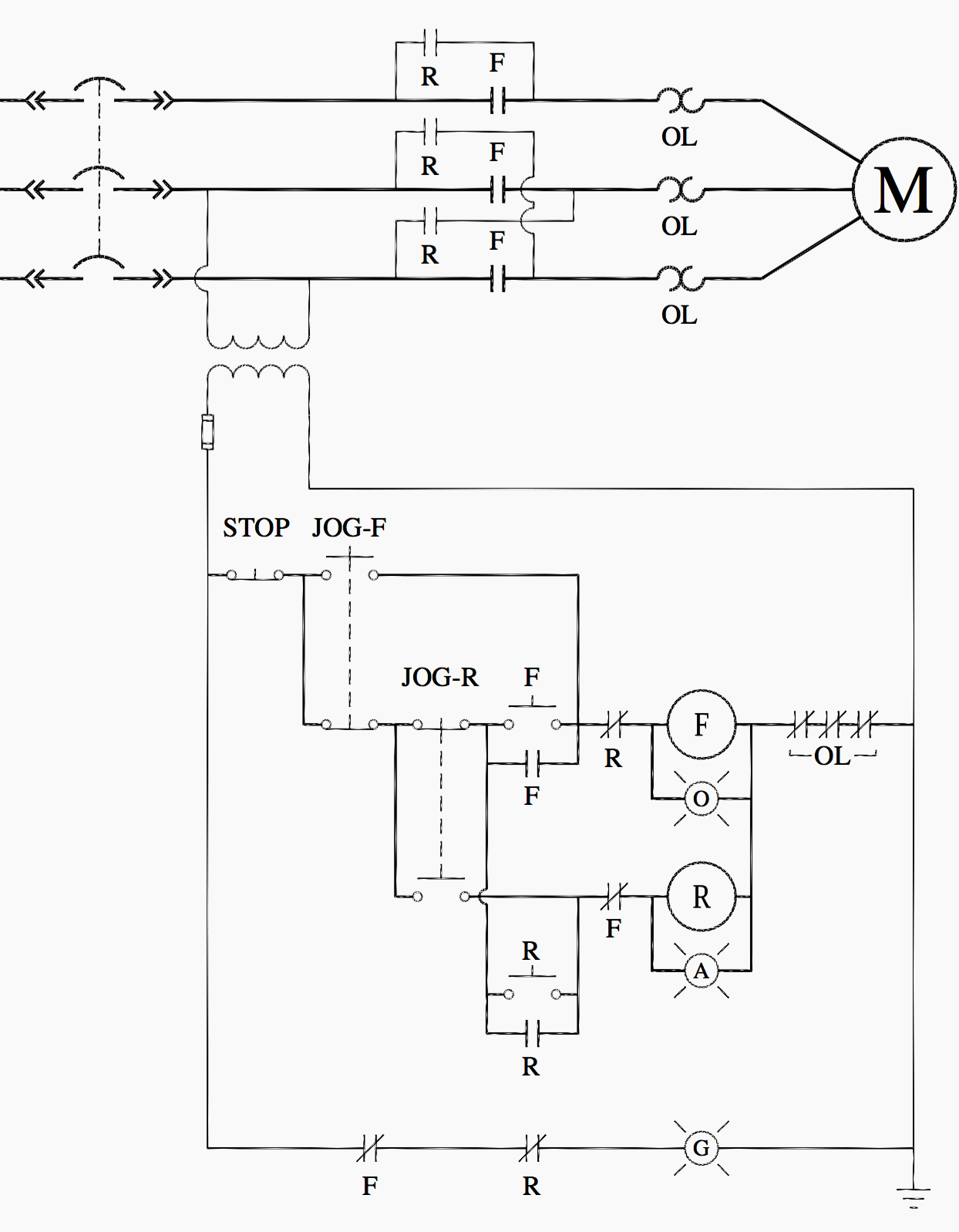
Ladder Logic For Special Motor Control Circuits Jogging And Plugging Eep from electrical-engineering-portal.com A relay is an electrically operated switch. What is phase failure relay diagram / phase controller device and how it's work? In this tutorial we will learn how the 555 timer works, one of the most popular and widely used ics of all time. Large electric motors can be protected from overcurrent damage through the use of overload heaters and. C1, c2, c3 = contatcors (for power & control diagram) o/l = over load relay The 555 timer ic was introduced in the year 1970 by signetic corporation and gave the name se/ne 555 timer. The lights stay on after parking car, and then. You can watch the following video or read the written tutorial below.
A relay is a switch that is operated by electricity. You can watch the following video or read the written tutorial below. Switches are made to handle a wide range of voltages and currents; The 555 timer ic was introduced in the year 1970 by signetic corporation and gave the name se/ne 555 timer. Ql series electromechanical relay specifications.
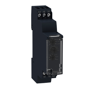
Re17rmmu Modular Timing Relay 8 A 1 S 100 H 1 Co 10 Functions 24 240 V Ac Schneider Electric Global from download.schneider-electric.com With the main contactor then when the timer reaches its time limit the star contactor. Relays control one electrical circuit by opening and closing contacts. Ladder diagrams differ from regular schematic diagrams of the sort common to electronics technicians primarily in the strict orientation of the wiring: You can watch the following video or read the written tutorial below. The world's largest high service distributor of electrical, automation description: Read about contactors (electromechanical relays) in our free electronics textbook. Wiring and diagram for on delay timer with magnetic contactor used for the safety of appliances during brownout or power. 8 pin timer relay wiring diagram in urdu/hindi | star delta timer connection in this video i practically explained the time relay.
C1, c2, c3 = contatcors (for power & control diagram) o/l = over load relay
This would be done in 12v and the sequence will be initiated by a the shown diagram is pretty straightforward yet provides the necessary actions very impressively, moreover the delay period is variable making the. Contactors and relays are electric switches. Video on long duration timer circuit diagram. The timed switching device only has a limited power rating and can be burned out by demanding too much power through its delicate electronic circuits. Switches are made to handle a wide range of voltages and currents;
Relay Wikipedia from upload.wikimedia.org C1, c2, c3 = contatcors (for power & control diagram) o/l = over load relay Using an ohmmeter, test between 2 testing compressor contactor. Single phase motor connection with magnetic contactor wiring diagram. Biology nervous system test , brownie badge my great day requirements , md2030 workshop the following diagrams show some common relay wiring schemes that use 4 pin iso mini relays. Types, working and difference between them. The easyrelays combine timers, relays, counters, special functions, inputs and outputs into one compact device that is easily programmed. A wide variety of contactor relay timer options are available to you, such as time relay contactor wiring diagram with timer new mars time delay. Special function flasher timing relay.
Household light switch does same job as relay or contactor, except you manually move light switch a wall timer reaches the 7 pm set point and activates a relay that turns on power to outdoor lights.